|
Academy F/A-18C Hornet
Construction Review Part Four
Aft Fuselage
by Dave Roof
|
 |
|
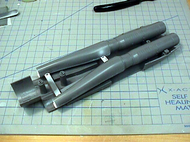
Engines and Intakes Installed in the Lower Fuselage |

Academy's 1/32 scale F/A-18C
Hornet may be ordered online from Squadron.com
The kit is coming along nicely. Today I will cover the
assembly of the aft fuselage section. This entire area went together with no
problems at all. The engineering of the kit almost forces a perfect kit among
the large components. Academy really raised the bar with this one. On to the
assembly!
Aft Fuselage
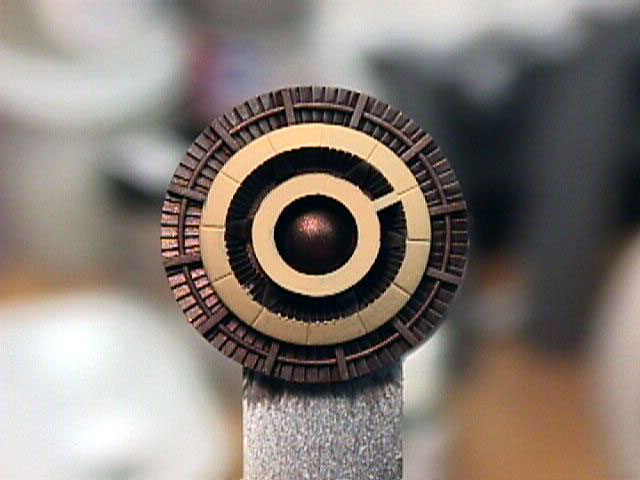
Photo 1 (11): I first painted the aft end of the engine Model Master
Metalizer Burnt Iron. The 'Flame Holder' was painted using Model Master Armor
Sand FS30277. Once this was dry, I glued it into place inside the engine
halves.
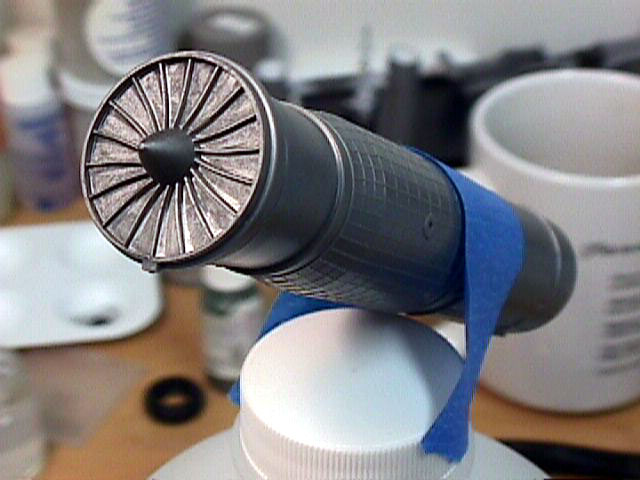
Photo 2 (12): Here is one of the engines assembled. When the engines are
inside the fuselage, no part of them can be seen. For this reason, I chose not
to paint them. The engine compressor blades were painted using Model Master
Metalizer Steel.
Photo 3 (13): The engines and intakes installed into the bottom fuselage half.
I would recommend using a slow setting glue to attach the engines to the
intakes, and use modeling clay or something similar to hold the engines while
the glue sets.
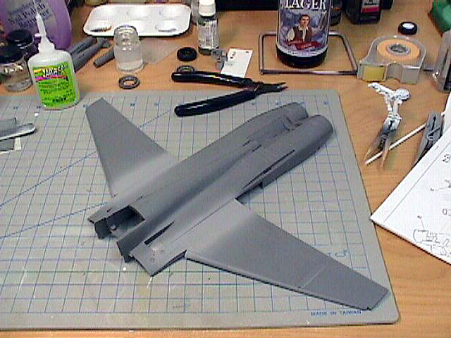
Photo 4 (14): Here is the upper aft fuselage half with the wings attached. The
wings attachment points are designed in such a way that the wings almost
'lock' into place.
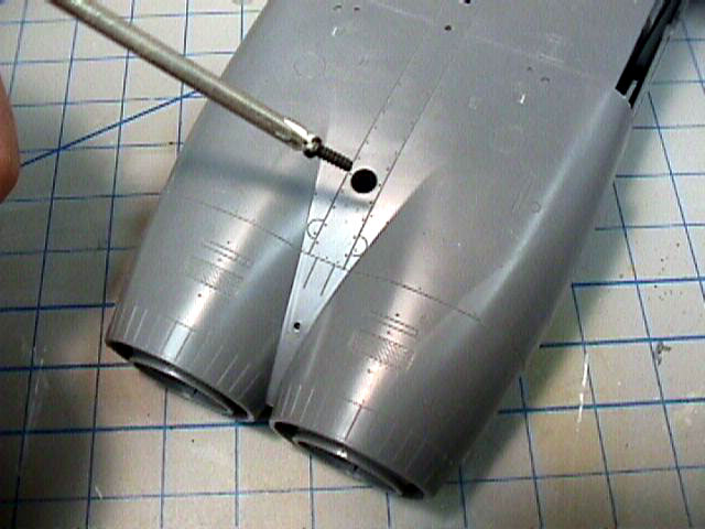
Photo 5 (15): Once the intakes, engines, and wings are secured and the glue
has set, I attached the upper aft fuselage half to the bottom. Three screws
are used to secure them together. A small screwdriver is also provided in the
kit.
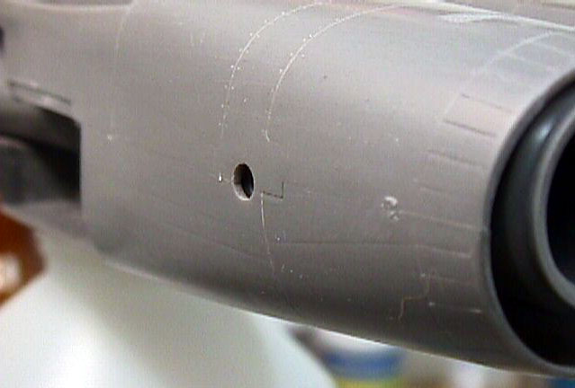
Photo 6 (16): Here is the fuselage joint sanded smooth. I use super glue
exclusively for all of my filling and assembly. Very little was needed to fill
the joints here.
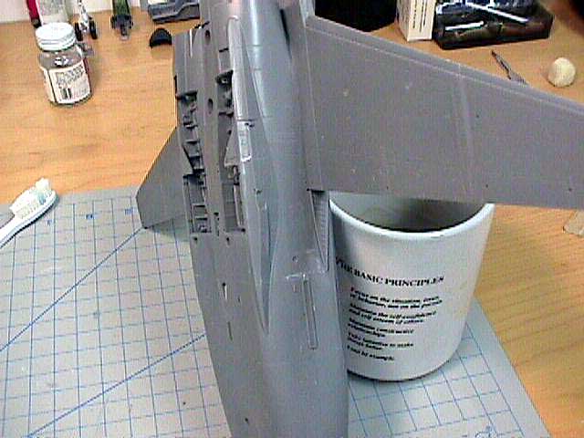
Photo 7 (17): While it is difficult to see in this photo, the fit of the aft
fuselage components was almost perfect. No extra filler, other than the glue
used to attach the parts, was needed in this area.
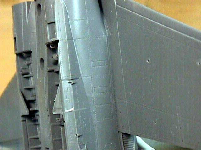
Photo 8 (18): A close up of the lower wing to fuselage joint. This was a
perfect fit on both sides.
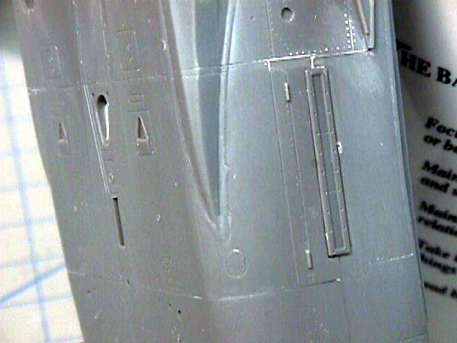
Photo 9 (19): Here is a close up shot of the formation strip light on the left
side of the aft fuselage. The strip lights for this area are separate pieces
and fit very well.
Well, that about does it for this portion of the aft fuselage section. I'll
cover the assembly of the forward fuselage section, as well as attaching it to
the aft section in Part 5.
Text and Images Copyright © 2003 by
Dave Roof
Page Created 08 April, 2003
Last updated 15 August, 2003
Back to HyperScale Main Page
|
 Home | What's
New | Features
| Gallery |
Reviews | Reference
| Forum
| Search
Home | What's
New | Features
| Gallery |
Reviews | Reference
| Forum
| Search