|
A-10A
"Warthog"
Trumpeter

Trumpeter's
1/32 scale A-10A Warthog is available online at Squadron.com
S
u m m a r y
|
| Catalogue Number
and Description: |
02214 - A-10A |
| Scale: |
1/32 |
| Price: |
Approximately AUD$170-$190 (USD
$85-$100) |
| Contents and Media: |
See Text for detail |
| Review Type: |
Review |
| Advantages: |
Impressive subject; excellent
surface detail; appropriate use of multi-media (resin engines,
white-metal undercarriage etc); |
| Disadvantages: |
Poorly positioned locating pins;
cockpit detail poor - not up the standard of the rest of the kit; centre
mould line on canopy |
| Recommendation: |
Highly Recommended |
Reviewed by
Terry Ashley
Some may call it ugly, but the A-10 "Warthog" has appeal due to its
uncompromising approach to the job at hand, its design and functionality. And
don't forget that the jocks who fly the Hog do just that - "fly it" -
unaided by sophisticated computers to get them out of trouble.
Being on the wrong end of the GAU-8/A or its missile arsenal is not the place
to be, as two helicopters and many hulks littering the Kuwaiti Desert will
testify!
Trumpeter's 1/32 scale A-10A comes in a big box as you might imagine.
The parts are tightly packed to fit them all in.
There are 437 light grey parts on 23 sprues including 5 sprues of
ordnance.
The two engines are in resin with the undercarriage legs, boarding ladder and
pitot tube in white metal. As with any white metal parts there are mould lines,
which you need to lightly file off.
The tires are in vinyl with nice tread pattern. 3 sprues of clear parts for
the windscreen, canopy, Maverick and Pave Penny heads and the engine nacelle
parts. A small length of twine for the wheel chocks and some metal parts (rearview
mirrors) and hinge parts for the engine nacelles. Two decal sheets are included,
one with the aircraft markings and the other with heaps of stencil data for the
ordnance. (Although the printing on the stencils is a little blurred for this
scale).
It is interesting that the strip lights, which were on the scans of the decal
sheets we saw some time back, are not included on these sheets. The TwoBobs
decal sheet for LASTE equipped Hogs includes these strips, so this is no real
problem. Also in my sample kit is the additional decal sheet for the A-10A N/AW
kit, I'm not sure if this will be in the A-10 kits that hit the shops.
The moulding of the details on the parts is crisp with engraved panel lines
and details as well as the raised rivet detail on the rear fuselage (as it
should be). The rear fins also feature the right combination of flush rivets to
the front and raised to the rear, very well done by Trumpeter here. The plastic
is very soft which makes for easy cutting, but easy to cut too much when
trimming parts, so take care. There is a small amount of flash around the edges
of some of the larger parts which will require careful removal.
The layout of the parts is conventional with fuselage halves, wings halves
and rear stabilizers and fins in halves with separate control surfaces. The
fuselage is split into rear and forward sections obviously for the two-hole N/AW
version. The kit features the additional "bumps" for the LASTE
(Low-Altitude Safety and Targeting Enhancement) on the fins and the GPS antenna
dome on the fuselage spine. It should be noted that these are not fitted to Gulf
War Hogs, so if you choose to model an A-10 from that period these will have to
be removed from the kit parts. This is certainly better than having to add them,
another tick for Trumpeter.
Please note that the kit is being built straight out of the box for use by
the Distributor as a display model at trade shows. I will though note areas
where additions or corrections can be included in the kit.
One general comment here regarding the locating pins on some parts when
mating two sides together (i.e. pylons, ordnance). A number of these were more a
hindrance than help. A quick dry fit of each before gluing would identify any
problems, I simply removed any pins that did not line up and then glued the
parts direct. I used Tenax-7R throughout with no problems, except of course for
the resin and metal bits where Cyanoacrylate was used.
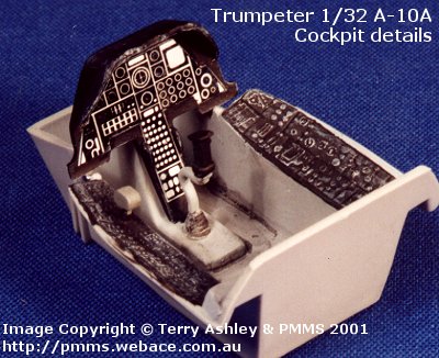
Cockpit and
Ejection Seat
 Construction
is straightforward. A full armored tub into which fits the actual cockpit tub is
supplied, although the detail here is very basic and not up to the standard of
the rest of the kit (Click the thumbnail to the left
to view cockpit detail full-sized). Construction
is straightforward. A full armored tub into which fits the actual cockpit tub is
supplied, although the detail here is very basic and not up to the standard of
the rest of the kit (Click the thumbnail to the left
to view cockpit detail full-sized).
The instrument panel is a decal that is too small to fit the panel coaming.
Furthermore, the side consoles have very 'soft' details. There is no foot pedals
and the control column is incorrect. It looks like they got the junior mould
maker to do the cockpit while the masters did the rest.
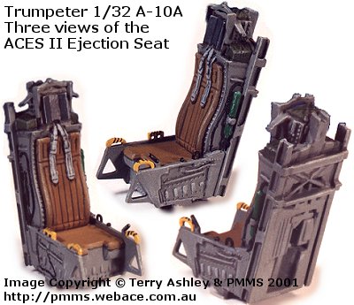 The
seat on the other hand is just the opposite and is one of the best seats I
have seen as standard in a kit for some time. It is made up of 7 pieces
with the oxygen bottle as a separate part and all that is needed is the
addition of the lap seat belts and with careful painting a very nice ACES
II will result. The
seat on the other hand is just the opposite and is one of the best seats I
have seen as standard in a kit for some time. It is made up of 7 pieces
with the oxygen bottle as a separate part and all that is needed is the
addition of the lap seat belts and with careful painting a very nice ACES
II will result.
Make sure you finish the cockpit and position it inside the armoured
tub before attaching the rear bulkhead (part N14) as it will not fit in
afterwards. The least said about the pilot figure the better, buy who
builds kits with pilots included anyway.
The area behind the seat is simple as per the real thing. You will have
to add the thermos bottle hoops and plumbing yourself though. The canopy
and windscreen are moulded very thin and clear with a centre mould line on
the canopy. Only the forward 10mm of this has to be removed as can easily
be seen on the part, the rest is left as per the real canopy. The front
flat windscreen has the correct square profile at the bottom, not rounded
as per the kit box illustration. Don't forget this has to be blue tinted
when painting the kit. The canopy raising mechanism is in two parts and
actually moves. You get rear view mirrors (metal part) for inside the
canopy as well as the two instruments inside the windscreen. |
The GAU-8A
Avenger
This is a very well detailed and straightforward assembly with 35 parts. The
only real problem here is the ammo belts are given as lengths of shells only
while they should be inside a metal wrap around feed belt. I suspect Eduard is
working on this right now.
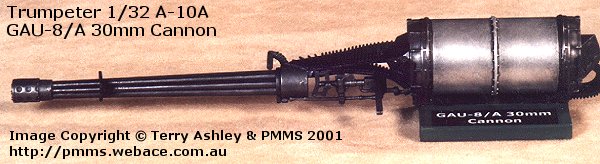
Care should be taken when assembling the ammo drum to ensure you put the drum
the right way around on the lower support (part R17). Also remember to add the
80g weight inside the drum if you want your Hog to stand on it's own three feet.
It's a pity this lovely assembly is completely hidden when installed inside the
fuselage, you can of course display this outside the finished model. As only one
muzzle is provided you will have to make a choice to install or show separate
Note, the small base is a display stand made from plastic beam and card.
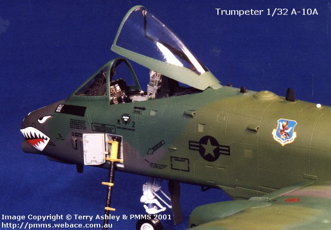
Forward Fuselage
The surface detail is superb with nice engraved lines and all the intake and
outlets moulded as separate pieces allowing the openings to be depicted open.
The boarding ladder door is also separate and you get a white metal 'round
profile' boarding ladder to fit here. The nose gear bay has nice details moulded
on with plenty of room to add all that extra plumbing that lives in this bay.
The refueling door is a separate part so as not to compromise the detail when
joining the fuselage halves. The ALR-69 RWR antenna have their bases moulded
into the fuselage halves with clear parts for the center 'bumps'.
The fit of the two fuselage halves was excellent with only minor seam cleanup
needed. Unfortunately the cockpit assembly again provided problems. This hole
assemble just seems out of context with the rest of the kit as I mentioned
earlier and this extends to fitting it between the fuselage halves. The mounting
lugs on the fuselage halves just didn't line up with those on the cockpit tub, I
ended up removing the mounting lugs and positioning the tub manually for the
best fit after many dry fittings. The instrument panel didn't match too well
with the forward coaming either. Remember to add an extra 80g of weight anywhere
inside the front fuselage as well as that inside the ammo drum. I choose to
leave out the cannon assembly for display purposes, but dry fitting seemed to
indicate no problems would be encountered. If you do this add the 80g of weight
from the ammo drum in the fuselage where the drum would normally go.
The lower wheel well section was then fitted in place, a bit of filler was
needed on a couple of the corners but nothing excessive. The way they have
engineered the air intake below the cannon as part of the wheel well assembly
results in the correct opening when the sections are fitted together, very nice.
Although there is a mounting pin lug just inside the opening which can be seen
when assembled, it may be better to remove this lug before hand so it is clear
through. Added to the fuselage is a number of separate intakes and antennas,
ensuring these are cleaned up before fitting will see no problems. I left off
the nose-boarding ladder and door until after painting.
Rear Fuselage,
Stabiliser and Fin Assembly
This again has excellent surface detail with the rivets changing from flush
to raised from just behind the wing trailing edge as it should be. Again the RWR
antennas are as per the forward fuselage. The horizontal stabilizers and
vertical fins have separate control surfaces including separate trim tabs. These
are also all designed to move and finally the rudder actuator rod is again a
separate part for even more detail. The engine nacelle's are in six parts with
separate doors to allow the engine details to be seen, these doors have fine
metal hinges to allow them to operate. More on this in the engine section below.
The join between the nacelle assembly and the rear fuselage will require a bit
of work on the undersides, but the join between the nacelles and front cowling
ring is spot on.
Apart from the usual cleanup of the join line seams there were no problems
here. The fit of all parts was excellent with the fit of the stabilizer unit to
the rear fuselage being exceptionally good with no filler needed. I did add
reinforcing strips between the forward halves of the rear fuselage (parts C3
& C4). This is because these fit over the lip of the front fuselage and I
didn't want the seam 'popping' open if the fit was a little too snug.
Mating the
Forward and Rear Fuselage
One thing I noticed when fitting the front and rear fuselage sections to
together was the lip on the front section tended to try and "force"
open the rear halves. I removed half the depth of the lip and it fixed the
problem still leaving enough overlap to ensure a good bond. The all important
join between the front and rear fuselage sections sees the join between the
overlapping trailing edge fairing (on the rear fuselage parts) to the forward
fuselage sides spot on, as good as you will see anywhere. The top join will
require a bit of filler but overall the edges match perfectly all around.
Undercarriage
These are all solid metal castings and a good thing to as this is rather
heavy model with the 160g of nose weight needed. The castings are good quality
with the usual casting seems to be filed off, but nothing excessive. All the
major fittings are provided, e.g. steering and landing lights on the nose leg.
The large amount of plumbing on the legs will need to be added from various
thickness of wire as none is provided. You are provided with screws to attach
the wheel hubs to the legs, these proved to a royal pain in the butt. So much
force was required to actually screw these into what is fairly solid metal
resulted in two of the screw heads snapping off. It is far simpler to just
Cyanoacrylate them to the axles.
The fitting of the legs to the locating holes in the nose and wings is very
snug and would actually happily sit in place without and Cyanoacrylate being
applied, but I'd still glue them. I did in fact leave the legs off until after
final painting. The gear doors that attach to the main legs are a little on the
thick side and could be reduced a far bit for a better appearance. There is also
some nasty pin ejector marks on the inside of the gear doors that are difficult
to remove owing to the detail on the doors.
Wings
The wings are moulded in upper and lower halves with excellent surface
details. The Fowler flaps are in separate upper and lower pieces (both inner and
outer flaps) and designed to move in and out as per the rear aircraft. The
instructions should be followed when installing the flaps and there shouldn't be
any problems.
The aileron/speed brakes are also in upper and lower halves and again
designed to move, there is an inner bulkhead (spar) to fill the hole if you show
these open. The inboard slats can also be positioned open or closed. The wingtip
position light/strobe light is a separate clear part with excellent detail.
The main gear fairings have no internal details apart from panel lines
engraved on the lower wings that form the bottom of the bays. The real things
have very little inside them apart from the fuel plumbing on the port side and
some internal wiring. The fit of these fairings around the front ends is a mess.
The top fairing on the starboard wing is the wrong shape, but the shape of the
lower fairing (part M1) is OK, so you can use this as a guide to fill and
reshape the upper part. The side joins forward of the leading edge doesn't match
too well either and some filler will be needed here. The refueling panel on the
port fairing is also the wrong shape, the break should be facing forward on a
steeper angle with a small lip at the bottom and not straight across as in the
kit. The wing fences inboard of the wheel fairing will need replacing, as they
are the wrong shape, obviously a casualty of moulding restrictions. This all
sounds like a lot of work, but overall the wing assembly has excellent details
in the surface detail and shape.
The rear chaff/flare dispensers are nicely detailed but appear to be slightly
too narrow, but you have to be really picky to notice this on the finished kit
as they are facing down. The side profile appears to be OK.
The underwing pylons are each in two halves and "sit" in small
recesses on the bottom wing, while the three fuselage pylons sit flush with the
bottom fuselage and they each have sway braces as separate parts.
The joins between upper and lower wings is good dimensionally, but again a
little "soft" at the edges and will require some filler, especially
the underside of the wingtips inside of the downward sweep. This join has been a
problem on every A-10 kit I have seen (i.e. 1/48 Tamiya and Monogram).
TF-34 Engines
and Nacelles
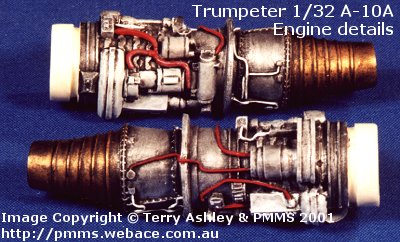 The
resin engines are excellent with nicely defined details. They include the
larger fuel lines and some other plumbing, but there is considerable scope
to add the myriad of smaller cabling that surrounds the real things. The
front turbine blades and engine surrounds are moulded clear, the blades
having gaps between them on the moulding. The
resin engines are excellent with nicely defined details. They include the
larger fuel lines and some other plumbing, but there is considerable scope
to add the myriad of smaller cabling that surrounds the real things. The
front turbine blades and engine surrounds are moulded clear, the blades
having gaps between them on the moulding.
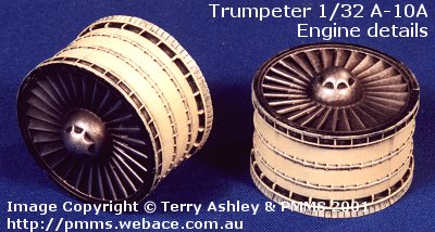
The outer mounting 'cocoon' is also provided as two clear pieces, which
trap the resin engine between them. This results in you viewing the engine
through the clear parts if the nacelle doors are shown open. On the real
aircraft sections of this inner mounting open as part of the nacelle door
allowing direct access to the engines. To represent this on the model
would require parts of the inner clear part being cut away and attached to
the inside of the nacelle door, not an insurmountable task but would
require a bit of work. |
|
 One
nice feature on the two clear cocoon parts are four stubs which when
fitting inside the front intakes ensure the engine is seated exactly
centrally, eliminating any lineup problems. One
nice feature on the two clear cocoon parts are four stubs which when
fitting inside the front intakes ensure the engine is seated exactly
centrally, eliminating any lineup problems.
With careful painting the engines assembles scrub up very nicely. I
also painted the inner halves of the clear cocoons Matt black to eliminate
the see-though look when viewing the engines. These assemblies fit snugly
into the engine nacelle halves with the front intake ring all fitting
together well with only a minor amount of cleanup along the seams needed,
no more than is usual.
The nacelle doors are hinged using small metal fittings, which you
attach with Cyanoacrylate. |
Ordnance
Including in the kit are these items:
-
2 x AIM-9L/M Sidewinders and one ALQ-119 ECM
pod,
-
2 x BLU-27 napalm canisters, 2 x Mk. 20 Rockeyes,
-
6 x CBU-52s,
-
a single GBU-10 Paveway and GBU-8 TV guided bomb
(with clear nose),
-
6 x AGM-65 Mavericks (again with clear seeker
heads)
-
12 Mk.82 LDGPs (these unfortunately are pretty
sad) and finally
-
one center line fuel tank.
The Mavericks come with triple launch rails although there is an amendment in
the instructions, which also show the single launch rail most commonly used on
Deserts Storm Hogs. I couldn't find this part in my kit. Maybe, as it is a
sample, the production kits will most likely include these extra parts. Included
is two MERs but no TERs. Unfortunately the Hog doesn't use the MERs except for
training sorties while the TERs are used operationally. This means TERs will
have to be found elsewhere. The Ordnance in general is the poorest part of the
kit with some of the details being on the basic side.
If you thought you were going to paint this monster in one evening forget it
- this is a big job.
I used Model Master Enamels #1713 FS34102, #1764 FS34092 and #1788 FS36081
and Humbrol enamels for the finer detail painting.
One point to note before commencing painting is that the Euro 1 painted Hogs
had different pattern cam schemes during their life. The same three colours were
used but the pattern differed.
The Hogs during Desert Storm had a different pattern than post DS Hogs with
the later LASTE additions. The painting diagram in the kit instructions is
basically for the DS aircraft but a little different from what is in most
photographs.
The instructions with the Monogram 1/48 Hog have a typical layout for the pre
and DS A-10s. The colour cam scheme in the Squadron Signal Walkaround book
(#5517, page 69) on the A-10 is for a post DS Hog before they were progressively
repainted in the current two gray scheme. I choose to use the later Euro 1
scheme as the kit has the LASTE mods and information suggests the kit decals for
EL 209 depict an aircraft that wasn't actually used during Desert Storm. It is
best to check you references closely before deciding which scheme to use.
After masking off the cockpit, engines and gear bays (a job in itself), I
airbrushed the Medium Green (FS34102). This was the easy part as you can
liberally apply the green without having to worry about adjoining colours. The
Dark Green (FS34092) and Gray (FS36081) followed this. I actually painted the
model in three sessions mainly due to the full wraparound scheme holding the
model while painting became a problem, it was also a bit of fun airbrushing the
cam around the engine nacelle area.
Once completed and fully dry, I then glossed the areas to receive decals,
which lets face it on a modern jet is most of it. You get a nice selection of
stencils on the decal sheet (NO STEPS and lifting symbols plus the many data
blocks on the forward fuselage).
These are extremely thin and well printed (except for the stencils on the
ordnance, where some are just blobs meant to represent writing). A number of the
decals are in multiple parts to overcome any colour registering problems.
The unit insignia on the tail and fuselage have two and three decals
respectively; this is a good idea as any misalignment is then your fault (sorry
guys). The thinness of the decals means they react very well to decal setting
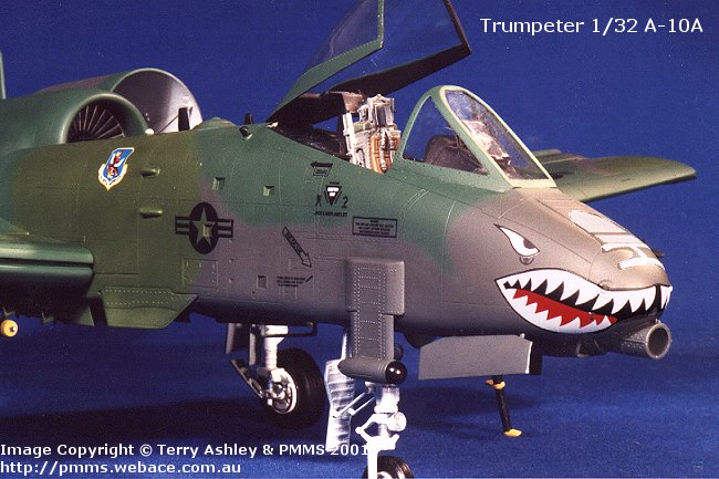
solution and really suck down around the surface details. The way the shark
mouth decal sucked down around the nose RWR antennas was stunning. It also means
you have to be careful when sliding the decal from its backing sheet onto the
model as it is very easy to destroy the decal.
These are some of the best decals I have seen as stock kit decals. They are
light years ahead of the overly thick stuff we get in Tamiya and Hasegawa kits.
Why the data blocks on the ordnance decals are such a mess is strange as the
data blocks for the aircraft itself are all fully legible.
The instructions are well laid out and easy to follow. They also feature
tables showing the different weapons configurations and detailed painting guides
for all the ordnance. Four view drawings are given for the Euro 1 paint scheme
along with FS numbers for the paints and locations of the stenciling provided.
Additional side views drawings show the placement of the unit markings. These
consist of two aircraft shown below. The hogs teeth on the NO machine are white
and red on the decal sheet, but light brown in the illustration in the Squadron
Signal A-10 walkaround book.
I have included here scans of the Instruction Sheets. This hopefully will
give you a better idea of the detail and layout of the kit.
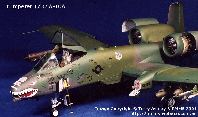
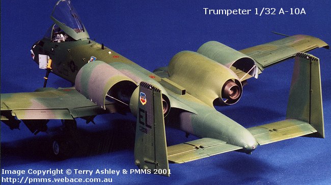
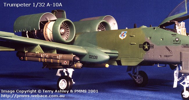
Photos of the painted model. Please note, as I mentioned ealier this model is
built straight from the box for use at trade shows by the distributor. The model
was required for one of these shows before I was able to finish the weathering
of the model. When it is returned, hopefully in one piece I will complete the
weathering and other minor bits and update the review with the pictures.
This is a sensational kit, but like any kit there are areas that need
attention. You will need to use some old fashioned modelling skills in places.
Despite some minor fit problems and a bit of flash about the place, it takes the
points with some brilliant surface and other details and and will build into a
stunning model.
I have not compared the kit to any plans, never have, never will. I use the
Mk.1 eyeball to check for errors. If you can't see something by comparing to
reference photos then it's probably so small as not to worry about. I'll leave
the rivet counting to those better qualified.
For another opinion on this excellent kit, check Steve Filak, Sr's review at Aircraft
Resource Center. You will also find some excellent Walkaround photos of the
A-10 in their Walkaround section. You will also find a good build review by Jack
Mugan with plenty of pictures at Rollmodels.com
NEWS: Black Box are to release a cockpit update set for this kit. It will
include tub, floor, rear bulkhead, instrument panel/coaming, throttle, control
stick, rudder pedals, turtle deck, ACES II, two-piece canopy actuator (like the
BB 1/48 scale set), and insert below the two cutouts on the turtledeck. Release
date, tentative early April. More news when known.
Highly Recommended.
Review Copyright © 2001 by Terry
Ashley and PMMS
Page Created 28 March, 2001
Last updated 09 November, 2003
Back to HyperScale
Main Page
Back to Reviews
Page
|
 Home | What's
New | Features
| Gallery |
Reviews | Reference
| Forum
| Search
Home | What's
New | Features
| Gallery |
Reviews | Reference
| Forum
| Search